
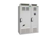
Schneider Electric Variable speed drive, Altivar Process ATV600, Compact System ATV660, 800/630 kW, 400 V, IP23; ATV660C80Q4X1
Variable speed drive, Altivar Process ATV600, Compact System ATV660, 800/630 kW, 400 V, IP23; ATV660C80Q4X1...
Cena na upit
Variable speed drive, Altivar Process ATV600, Compact System ATV660, 800/630 kW, 400 V, IP23; ATV660C80Q4X1
| Range of produc | Altivar Process ATV600 |
|---|---|
| Product or component type | Variable speed drive |
| Product specific application | Process and utilities |
| Device short name | ATV660 |
| Product destination |
Synchronous motors Asynchronous motors |
| Assembly style | In floor-standing enclosure compact version |
| Provided equipment |
Enclosure Spacial SF Graphical operating panel in the enclosure door Frequency inverter Main switch Line choke Terminal block main supply Terminal block motor |
| Cable entry | Bottom |
| Colour of enclosure | Light grey (RAL 7035) |
| IP degree of protection | IP23 conforming to IEC 61800-5-1 |
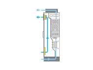
| Type of cooling | Forced convection |
| [Us] rated supply voltage | 380...415 V - 10...6 % |
| Supply frequency | 50/60 Hz +/-5 % |
| Network number of phases | 3 phases |
| Overvoltage category | III |
| Asynchronous motor control profile |
Variable torque standard Constant torque standard Optimized torque mode |
| Synchronous motor control profile | Permanent magnet motor |
| Output voltage | <= power supply voltage |
| Permissible temporary current boost |
1.1 x In during 60 s (normal duty) 1.5 x In during 60 s (heavy duty) |
| Nominal switching frequency | 2.5 kHz |
| Switching frequency | 2...8 kHz adjustable with derating factor |
| Speed drive output frequency | 0.1…500 Hz |
| Motor power kW |
800 kW for normal duty 630 kW for heavy duty |
| Continuous output current |
1420 A at 2.5 kHz for normal duty 1140 A at 2.5 kHz for heavy duty |
| Maximum transient current |
1562 A during 60 s per 10 min (normal duty) 1710 A during 60 s per 10 min (heavy duty) |
| Line current |
1335 A at 400 V (normal duty) 1061 A at 400 V (heavy duty) |
| Apparent power |
925 kVA at 400 V (normal duty) 735 kVA at 400 V (heavy duty) |
| Maximum THDI | <36 % full load conforming to IEC 61000-3-12 |
| Short-circuit protection |
Internal: 400.0 A 5 aR fuse Upstream: 1600.0 A gG fuse (normal duty) Upstream: 1250.0 A gG fuse (heavy duty) |
| Energy efficiency ratio | 0.98 |
| Power dissipation in W |
20600 W, total (normal duty) 15080 W, total (heavy duty) 2300 W, control part (normal duty) 1580 W, control part (heavy duty) |
| Volume of cooling air |
2900 m3/h for power 420 m3/h for control |
| Noise level | 74 dB conforming to 86/188/EEC - physical agents (noise) directive |
| Prospective line Isc | 50 kA for 100 ms |
| Electrical connection |
Removable screw terminals, clamping capacity: 0.5...1.5 mm² for control M12 bar for main supply M12 bar for motor |
| Motor recommanded cable cross section |
5 x (3 x 240 mm²) (normal duty) 6 x (3 x 185 mm²) (normal duty) 4 x (3 x 240 mm²) (heavy duty) 5 x (3 x 185 mm²) (heavy duty) 6 x (3 x 120 mm²) (heavy duty) |
| Width | 1400 mm |
| Height | 2150 mm |
| Depth | 664 mm |
| Net weight | 1100 kg |
| number of preset speeds | 16 preset speeds |
| communication port protocol |
Modbus TCP Modbus serial EtherNet/IP |
| Option card |
Slot A: communication module, Profibus DP V1 Slot A: communication module, PROFINET Slot A: communication module, DeviceNet Slot A: communication module, Modbus TCP/EtherNet/IP Slot A: communication module, CANopen daisy chain RJ45 Slot A: communication module, CANopen SUB-D 9 Slot A: communication module, CANopen screw terminals Slot A/slot B: digital and analog I/O extension module Slot A/slot B: output relay extension module |
| Safety function | STO (safe torque off), level SIL 3 for <= 100 ms |
| EMC filter |
Integrated conforming to EN/IEC 61800-3, category C3, shielded cable with 150 m Integrated conforming to EN/IEC 61800-3, category C4, unshielded cable with 250 m |
| Motor slip compensation |
Automatic whatever the load Not available in permanent magnet motor law Can be suppressed Adjustable |
|---|---|
| Acceleration and deceleration ramps |
S, U or customized Linear adjustable separately from 0.01 to 9000 s |
| Braking to standstill | By DC injection |
| Protection type |
Motor: thermal protection Motor: safe torque off Motor: motor phase break Drive: thermal protection Drive: safe torque off Drive: overheating Drive: overcurrent (between output phases and earth) Drive: overload (output) Drive: short-circuit protection Drive: motor phase break Drive: overvoltage (DC bus) Drive: line supply overvoltage Drive: line supply undervoltage Drive: line supply phase loss Drive: overspeed Drive: break on the control circuit Drive: short-circuit protection with semi-conductor fuse (main supply) Drive: fan monitoring |
| Frequency resolution |
Display unit: 0.1 Hz Analog input: 0.012/50 Hz |
| Connector type |
RJ45 (on the control block) for Modbus serial RJ45 (on the control block) for Ethernet IP/Modbus TCP |
| Physical interface | 2-wire RS 485 for Modbus serial |
| Transmission frame | RTU for Modbus serial |
| Transmission rate |
10/100 Mbit/s for Ethernet IP/Modbus TCP 4.8, 9.6, 19.2, 38.4 kbit/s for Modbus serial |
| Exchange mode | Half duplex, full duplex, autonegotiation Ethernet IP/Modbus TCP |
| Data format | 8 bits, configurable odd, even or no parity for Modbus serial |
| Type of polarization | No impedance for Modbus serial |
| Number of addresses | 1…247 for Modbus serial |
| Method of access | Slave Modbus TCP |
| Supply |
External supply for digital inputs: 24 V DC (10…30 V), <1.25 mA, protection type: overload and short-circuit protection Internal supply for reference potentiometer (1 to 10 kOhm): 10.5 V DC +/- 5 %, <10 mA, protection type: overload and short-circuit protection Internal supply for digital inputs and STO: 24 V DC (21…27 V), <200 mA, protection type: overload and short-circuit protection |
| Local signalling | LCD display unit front door operation function, status and configuration |
| analogue input number | 3 |
| Analogue input type |
AI1, AI2, AI3 software-configurable voltage: 0...10 V DC, impedance: 30 kOhm, resolution 12 bits AI1, AI2, AI3 software-configurable current: 0...20 mA, impedance: 250 Ohm, resolution 12 bits |
| Discrete input number | 8 |
| Discrete input type |
DI1...DI6 programmable, 24 V DC (<= 30 V), impedance: 3.5 kOhm DI5, DI6 programmable as pulse input: 0…30 kHz, 24 V DC (<= 30 V) STOA, STOB safe torque off, 24 V DC (<= 30 V), impedance: > 2.2 kOhm |
| Input compatibility |
DI1...DI6: discrete input level 1 PLC conforming to EN/IEC 61131-2 DI5, DI6: discrete input level 1 PLC conforming to IEC 65A-68 STOA, STOB: discrete input level 1 PLC conforming to EN/IEC 61131-2 |
| Discrete input logic |
Positive logic (source) (DI1...DI6), < 5 V (state 0), > 11 V (state 1) Negative logic (sink) (DI1...DI6), > 16 V (state 0), < 10 V (state 1) Positive logic (source) (DI5, DI6), < 0.6 V (state 0), > 2.5 V (state 1) Positive logic (source) (STOA, STOB), < 5 V (state 0), > 11 V (state 1) |
| analogue output number | 2 |
| Analogue output type |
Software-configurable voltage AQ1, AQ2: 0...10 V DC impedance 470 Ohm, resolution 10 bits Software-configurable current AQ1, AQ2: 0...20 mA, resolution 10 bits |
| Sampling duration |
2 ms +/- 0.5 ms (DI1...DI4) - discrete input 5 ms +/- 1 ms (DI5, DI6) - discrete input 5 ms +/- 1 ms (AI1, AI2, AI3) - analog input 10 ms +/- 1 ms (AQ1, AQ2) - analog output |
| Accuracy |
+/- 0.6 % AI1, AI2, AI3 for a temperature variation 60 °C analog input +/- 1 % AQ1, AQ2 for a temperature variation 60 °C analog output |
| Linearity error |
AI1, AI2, AI3: +/- 0.15 % of maximum value for analog input AQ1, AQ2: +/- 0.2 % for analog output |
| Relay output number | 3 |
| Relay output type |
Configurable relay logic R1: fault relay NO/NC electrical durability 100000 cycles Configurable relay logic R2: sequence relay NO electrical durability 100000 cycles Configurable relay logic R3: sequence relay NO electrical durability 100000 cycles |
| Refresh time | Relay output (R1, R2, R3): 5 ms (+/- 0.5 ms) |
| Minimum switching current | Relay output R1, R2, R3: 5 mA at 24 V DC |
| Maximum switching current |
Relay output R1, R2, R3 on resistive load, cos phi = 1: 3 A at 250 V AC Relay output R1, R2, R3 on resistive load, cos phi = 1: 3 A at 30 V DC Relay output R1, R2, R3 on inductive load, cos phi = 0.4 and L/R = 7 ms: 2 A at 250 V AC Relay output R1, R2, R3 on inductive load, cos phi = 0.4 and L/R = 7 ms: 2 A at 30 V DC |
| Isolation | Between power and control terminals |
| Insulation resistance | > 1 MOhm 500 V DC for 1 minute to earth |
|---|---|
| Operating position | Vertical +/- 10 degree |
| Electromagnetic compatibility |
Electrostatic discharge immunity test level 3 conforming to IEC 61000-4-2 Radiated radio-frequency electromagnetic field immunity test level 3 conforming to IEC 61000-4-3 Electrical fast transient/burst immunity test level 4 conforming to IEC 61000-4-4 1.2/50 µs - 8/20 µs surge immunity test level 3 conforming to IEC 61000-4-5 Conducted radio-frequency immunity test level 3 conforming to IEC 61000-4-6 |
| Pollution degree | 2 conforming to EN/IEC 61800-5-1 |
| Vibration resistance |
1.5 mm peak to peak (f= 3…10 Hz) conforming to IEC 60068-2-6 0.6 gn (f= 10…200 Hz) conforming to IEC 60068-2-6 3M3 conforming to IEC 60721-3-3 |
| Shock resistance |
4 gn for 11 ms conforming to IEC 60068-2-27 3M2 conforming to IEC 60721-3-3 |
| Relative humidity | 5…95 % without condensation conforming to IEC 60068-2-3 |
| Ambient air temperature for operation |
-10…0 °C without derating (with option enclosure heating) 0…40 °C without derating 40…50 °C with derating factor |
| Ambient air temperature for storage | -25…70 °C |
| Operating altitude |
< 1000 m without derating 1000...2000 m with current derating 1 % per 100 m 2000...3800 m with current derating 1 % per 100 m for TT earthing system 2000...3800 m with current derating 1 % per 100 m for TN earthing system 2000...3800 m with current derating 1 % per 100 m for IT earthing system 3800...4800 m with current derating 1 % per 100 m for TT earthing system 3800...4800 m with current derating 1 % per 100 m for TN earthing system |
| Environmental characteristic |
Chemical pollution resistance class 3C3 conforming to EN/IEC 60721-3-3 Dust pollution resistance class 3S3 conforming to EN/IEC 60721-3-3 Humidity resistant class 3K3 conforming to EN/IEC 60721-3-3 |
| Standards |
EN/IEC 60204-1 EN/IEC 61800-2 EN/IEC 61800-3 EN/IEC 61800-5-1 |
| Product certifications |
ATEX EAC C-Tick |
| Marking | CE |
-

Schneider Electric Altivar-Process-ATV600 ATV660C80Q4X1
Slicni proizvodi:
Schneider Electric increased protection degree IP54, Altivar Process ATV600, Altivar Process ATV900, for Drive Systems 710 to 800kW; VW3AP0305
increased protection degree IP54, Altivar Process ATV600, Altivar Process ATV900, for Drive Systems 710 to 800kW; VW3AP0305
-

(Trenutno nema na stanju)
Cena na upit

Schneider Electric increased protection degree IP54, Altivar Process ATV600, Altivar Process ATV900, for Drive Systems 355 to 500kW; VW3AP0303
increased protection degree IP54, Altivar Process ATV600, Altivar Process ATV900, for Drive Systems 355 to 500kW; VW3AP0303
-
(Trenutno nema na stanju)
127.094,80

Schneider Electric Pogon promenljive brzine, Altivar Process ATV600, ATV650, 250 kV, 400 ... 480 V, podni;ATV650C25N4F
Pogon promenljive brzine, Altivar Process ATV600, ATV650, 250 kV, 400 ... 480 V, podni
-
(Trenutno nema na stanju)
3.632.940,00
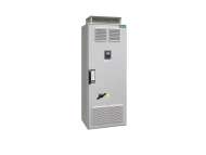
Schneider Electric Variable speed drive, Altivar Process ATV600, Compact System ATV660, 400/315 kW, 400 V, IP23; ATV660C40Q4X1
Variable speed drive, Altivar Process ATV600, Compact System ATV660, 400/315 kW, 400 V, IP23; ATV660C40Q4X1
-
(Trenutno nema na stanju)
4.338.042,00
Schneider Electric Pogon sa promenljivom brzinom, Altivar Process ATV600, ATV650, 315 kV, 400 ... 480 V, podno stajanje;ATV650C31N4F
Pogon sa promenljivom brzinom, Altivar Process ATV600, ATV650, 315 kV, 400 ... 480 V, podno stajanje
-
(Trenutno nema na stanju)
Cena na upit
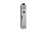
Schneider Electric Variable speed drive, Altivar Process ATV600, Compact System ATV660, 710/560 kW, 400 V, IP23; ATV660C71Q4X1
Variable speed drive, Altivar Process ATV600, Compact System ATV660, 710/560 kW, 400 V, IP23; ATV660C71Q4X1
-
(Trenutno nema na stanju)
Cena na upit